|
|
The ABS-ECU is energized by the valve power supply circuit (terminal No.26). When the power is supplied from the ignition switch (IG1) to the IG1 relay in ETACS-ECU, IG1 relay is turned on. At this time, the valve power supply circuit (terminal No.26) energizes the ABS-ECU.
|
|
|
This diagnosis code is set when the ABS-ECU power supply voltage is more than 18.0 ± 1.0 V.
|
|
|
- Battery failure
- ABS-ECU malfunction
- Charging system failed
|
|
|
Use M.U.T.-III to diagnose the CAN bus lines.
|
|
|
Q.
Is the check result normal?
|
|
|
 Repair the CAN bus lines (Refer to GROUP 54C - CAN Bus Diagnosis table Repair the CAN bus lines (Refer to GROUP 54C - CAN Bus Diagnosis table  ). On completion, go to Step 2. ). On completion, go to Step 2.
|
|
|
|
|
|
Q.
Is the diagnosis code No. C2101 set?
|
|
|
This diagnosis is complete.
|
|
|
|
|
|
Visually check for open circuit in fusible link No.27.
|
|
|
Q.
Is the check result normal?
|
|
|
Replace fusible link No.27.
|
|
|
|
|
|
Refer to GROUP 54A - Battery Test .
|
|
|
Q.
Is the battery in good condition?
|
|
|
Refer to GROUP 16 - Charging System .
|
|
|
Q.
Is the charging system in good condition?
|
|
|
Repair or replace the charging system component(s).
|
|
|
|
|
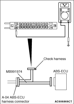
(1)Disconnect the ABS-ECU connector, connect special tool ABS check harness (MB991974) to the harness-side connector, and then measure the voltage at the special tool connector side.
| note |
Do not connect the special tool ABS check harness (MB991974) to ABS-ECU.
|
(2)Turn the ignition switch to the ON position.
(3)Measure the voltage between terminal No.26 and body earth.
OK: Approximately battery voltage
Q.
Is the check result normal?
 Go to Step 8. Go to Step 8.
Go to Step 7.
|
|
|
Q.
Is the check result normal?
|
|
|
The open or short circuit may be present in the power supply circuit. Repair the wiring harness between the A-04 ABS-ECU connector terminal No.26 and the fusible link No.27.
|
|
|
|
|
|
NO : Repair the defective connector.
|
|
|
|
|
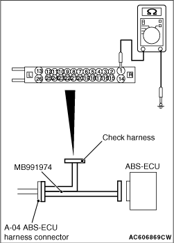
(1)Disconnect the ABS-ECU connector, connect special tool ABS check harness (MB991974) to the harness-side connector, and then measure the resistance at the special tool connector side.
| note |
Do not connect the special tool ABS check harness (MB991974) to ABS-ECU.
|
(2)Resistance between terminal No.1 and body earth, and between terminal No.14 and body earth.
OK: Continuity exists (2 Ω or less)
Q.
Is the check result normal?
Go to Step 10.
Go to Step 9.
|
|
|
Q.
Is the check result normal?
|
|
|
The open or short circuit may be present in the power supply circuit. Repair the wiring harness between the A-04 ABS-ECU connector terminal No.1 and body earth, and between the A-04 ABS-ECU connector terminal No.14 and body earth.
|
|
|
|
|
|
NO : Repair the defective connector.
|
|
|
|
|
|
Q.
Is the diagnosis code No. C2101 set?
|
|
|
Replace the ABS-ECU (Refer to ).
|
|
|
|
|
|
Intermittent malfunction (Refer to GROUP 00 - How to Cope with Intermittent Malfunction ).
|
|
|
|
)
)
)
)