|
|
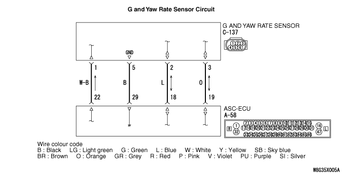
The G and yaw rate sensor outputs the signal to ASC-ECU via the special CAN bus lines.
|
|
|
This diagnosis code is set when the G and yaw rate sensor signal is not sent to ASC-ECU.
|
|
|
- Wiring harness or connector failure of CAN bus line
- G and yaw rate sensor malfunction
- ASC-ECU malfunction
- External noise interference
|
|
|
Use M.U.T.-III to diagnose the CAN bus lines.
|
|
|
Q.
Is the check result normal?
|
|
|
 Repair the CAN bus lines (Refer to GROUP 54C - Troubleshooting Repair the CAN bus lines (Refer to GROUP 54C - Troubleshooting  ). On completion, go to Step 4. ). On completion, go to Step 4.
|
|
|
|
|
|
Q.
Is the check result normal?
|
|
|
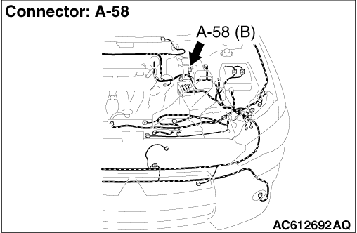
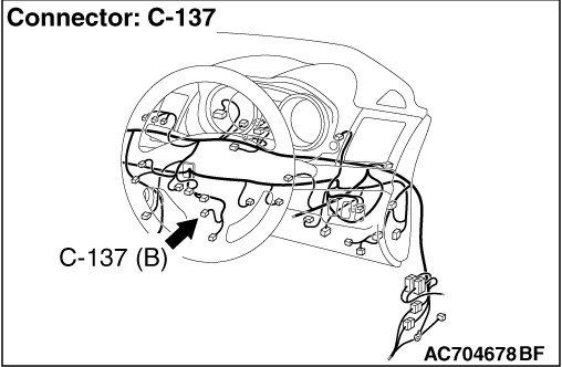
 Repair the connector, and then go to Step 4. Repair the connector, and then go to Step 4.
|
|
|
|
|
|
- Check for open circuit in communication circuit
|
|
|
Q.
Is the check result normal?
|
|
|
 Repair the wiring harness, and then go to Step 6. Repair the wiring harness, and then go to Step 6.
|
|
|
|
|
|
Q.
Is diagnosis code No.U0125 set?
|
|
|
 Replace the G and yaw rate sensor (Refer to Replace the G and yaw rate sensor (Refer to  ), and then go to Step 5. ), and then go to Step 5.
|
|
|
|
|
|
 This diagnosis is complete. This diagnosis is complete.
|
|
|
|
|
|
Q.
Is diagnosis code No.U0125 set?
|
|
|
 Replace the ASC-ECU (Refer to Replace the ASC-ECU (Refer to  ), and then go to Step 6. ), and then go to Step 6.
|
|
|
|
|
|
 The trouble can be an intermittent malfunction (Refer to GROUP 00 - How to Cope with Intermittent Malfunction The trouble can be an intermittent malfunction (Refer to GROUP 00 - How to Cope with Intermittent Malfunction  ). ).
|
|
|
|
|
|
Q.
Is diagnosis code No.U0125 set?
|
|
|
 This diagnosis is complete. This diagnosis is complete.
|
|
|
|


 Go to Step 2.
 Repair the CAN bus lines (Refer to GROUP 54C - Troubleshooting
  ). On completion, go to Step 4.
 Go to Step 3.
 Repair the connector, and then go to Step 4.
 Go to Step 4.
 Repair the wiring harness, and then go to Step 6.
 Replace the G and yaw rate sensor (Refer to
  ), and then go to Step 5.
 This diagnosis is complete.
 Replace the ASC-ECU (Refer to
  ), and then go to Step 6.
 The trouble can be an intermittent malfunction (Refer to GROUP 00 - How to Cope with Intermittent Malfunction
  ).
). Return to Step 1.
 This diagnosis is complete.