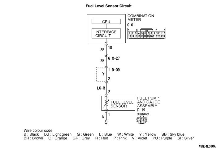
Code No.B1201: Fuel information error
| caution |
Whenever the ECU is replaced, ensure that the communication circuit is normal.
|
TROUBLE JUDGMENT
With the ignition switch at the ON position and the system voltage at 10 -16 V (data from ETACS-ECU), if the combination meter detects the abnormal resistance of fuel level sensor circuit for 64 seconds continuously, the diagnosis code No. B1201 is stored.
PROBABLE CAUSES
- Damaged harness wires and connectors
- Malfunction of fuel pump and gauge assembly
- Malfunction of combination meter
|
|
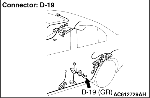
STEP 1. Connector check: D-19 fuel pump and gauge assembly connector
|
|
|
Q.
Is the check result normal?
|
|
|
 Go to Step 2. Go to Step 2.
|
|
|
|
|
|
 Repair the connector, and then go to Step 9. Repair the connector, and then go to Step 9.
|
|
|
|
|
|
STEP 2. Fuel pump and gauge assembly check
|
|
|
Check the fuel pump and gauge assembly. Refer to  . .
|
|
|
Q.
Is the check result normal?
|
|
|
Go to Step 3.
|
|
|
|
|
|
Replace the fuel pump and gauge assembly.
|
|
|
|
|
|
STEP 3. Check of fuel gauge (main) circuit
|
|
|
(1)Disconnect the D-19 fuel pump and gauge assembly connector.
|
|
|
(2)Use the special tool Check harness (MB991219) to connect a test lamp (12 V - 3.4 W) between the wiring harness connector terminals 1 and 2.
|
|
|
(3)Turn the ignition switch to the ON position.
|
|
|
(4)Check if the test lamp illuminates.
OK: Illuminates
|
|
|
Q.
Is the check result normal?
|
|
|
Go to Step 8.
|
|
|
|
|
|
Go to Step 4.
|
|
|
|
|
|
STEP 4. Resistance measurement at the D-19 fuel pump and gauge assembly connector
|
|
|
(1)Disconnect the fuel pump and gauge unit (main) connector, the measure at the harness side.
|
|
|
(2)Measure the resistance between the D-19 fuel pump and gauge assembly connector terminal No. 1 and the body earth.
OK: Continuity exists (2 Ω or less)
|
|
|
Q.
Is the check result normal?
|
|
|
Go to Step 6.
|
|
|
|
|
|
Go to Step 5.
|
|
|
|
|
|
STEP 5. Check the wiring harness between the D-19 fuel pump and gauge assembly connector terminal No. 1 and the body earth.
|
|
|
Q.
Is the check result normal?
|
|
|
Go to Step 9.
|
|
|
|
|
|
Repair the wiring harness, and then go to Step 9.
|
|
|
|
|
|
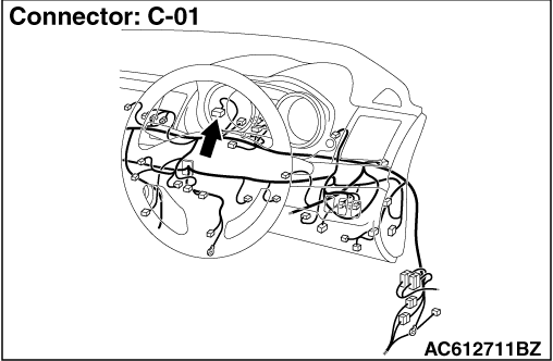
STEP 6. Connector check: C-01 combination meter connector
|
|
|
Q.
Is the check result normal?
|
|
|
Go to Step 7.
|
|
|
|
|
|
Repair the connector, and then go to Step 9.
|
|
|
|
|
|
STEP 7. Check the wiring harness between the C-01 combination meter connector terminal No. 18 and the D-19 fuel pump and gauge assembly connector terminal No. 2
|
|
|
| note |
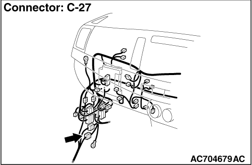
Before the wiring harness check, check the intermediate connectors C-27 and D-09, and repair them if necessary.
|
|
|
|
Q.
Is the check result normal?
|
|
|
Go to Step 8.
|
|
|
|
|
|
Repair the wiring harness, and then go to Step 9.
|
|
|
|
|
|
STEP 8. M.U.T.-III actuator test
|
|
|
- Item 03: Fuel gauge (target value): 0 →100%
|
|
|
OK: The fuel gauge operates.
|
|
|
Q.
Is the check result normal?
|
|
|
Go to Step 9.
|
|
|
|
|
|
Replace the combination meter
|
|
|
|
|
|
STEP 9. Check whether the diagnosis code is reset.
|
|
|
Check again if the diagnosis code is set to the combination meter.
|
|
|
(1)Erase the diagnosis code.
|
|
|
(2)Turn the ignition switch from "LOCK" (OFF) position to "ON" position.
|
|
|
(3)Check if diagnosis code is set.
|
|
|
Q.
Is the diagnosis code set?
|
|
|
Replace the combination meter
|
|
|
|
|
|
The diagnosis is complete.
|
|
|
|
)
)
)
)